Appendix
Electrical specifications
Input Voltage: J1 will accept a positive voltage on Pin 1 from 5-12 Volts DC. The input voltage is passed through up until about 5.7V or so, above which the regulator kicks in. Refer to the voltage regulator data sheet for details.
Operating Current: 60 mA nominal. The on-board regulator can provide up to 500 mA, so external circuitry connected to the expansion connectors can safely be powered from the regulator. Depending on the total current drawn, and the input voltage supplied to J1, heatsinking of the regulator may be necessary.
Operating Temperature Range: -20 C to +70 C (Note: the temperature range is limited mainly by the rating of the crystal. A broader range of -40 C to +85 C can be accommodated by using and extended-temperature range crystal or oscillator, or an external clock source.)
Board Dimensions: 3.25"(82.5mm) x 2.3"(58.5mm) x 0.75"(19mm), excluding connectors
Available Communications Interfaces (depending on configuration option):
- 2 x RS232C
- 1 x RS485
- 2 x CAN
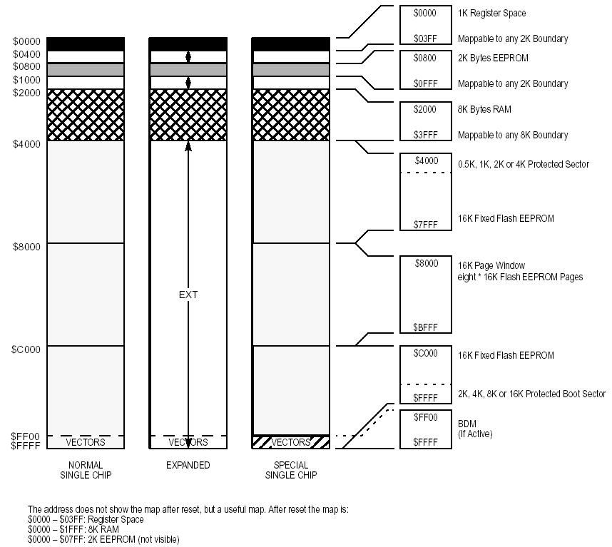
Example Memory Map for a Dx128 MCU
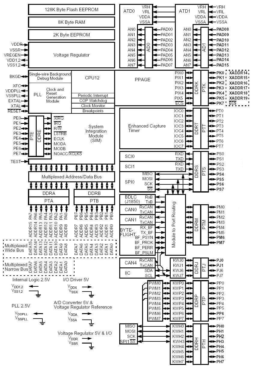
MCU Block Diagram (Dx128 family shown)
Notes on Serial Monitor
The "S" version of Adapt9S12D comes pre-programmed with a serial monitor in the topmost 2K of Flash memory. This monitor is from Freescale's Application Note AN2548. It is designed to function using the SCI0 interface at 115200 baud with a 16 MHz crystal, which it boosts to 24MHz using the PLL. Besides activating the PLL, it moves the RAM block and EEPROM block, via the INITRM and INITEE registers, to various addresses, depending on the MCU variant. To learn more about these details, or to customize options (such as which SCI to use, which port pin for the Load/Run selection, bus frequency, etc.), open the serial monitor project in CodeWarrior, where you can view and modify the .def and .asm files, as required. After building the modified project, the new s-record file will have to be burned into flash using a BDM pod (e.g. USBDMLT from Technological Arts). You'll find the the serial monitor project in the Technological Arts Support Library, at:
http://support.technologicalarts.ca/docs/Adapt9S12D/Code/