Appendix
Electrical specifications
Input Voltage: J1 will accept a positive voltage on Pin 1 from 6-12 Volts DC.
Operating Current: 60 mA nominal. Please note that the on board regulator is not designed to provide more than 500 mA without heatsinking.
Operating Temperature Range: -40 C to +85 C
Board Dimensions: 3.25" x 2.3", excluding connectors
Available Communications Interfaces:
- 2 x RS232C
- 1 x RS485
- 2 x CAN
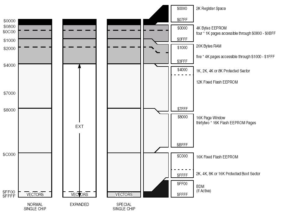
Memory Map Diagram
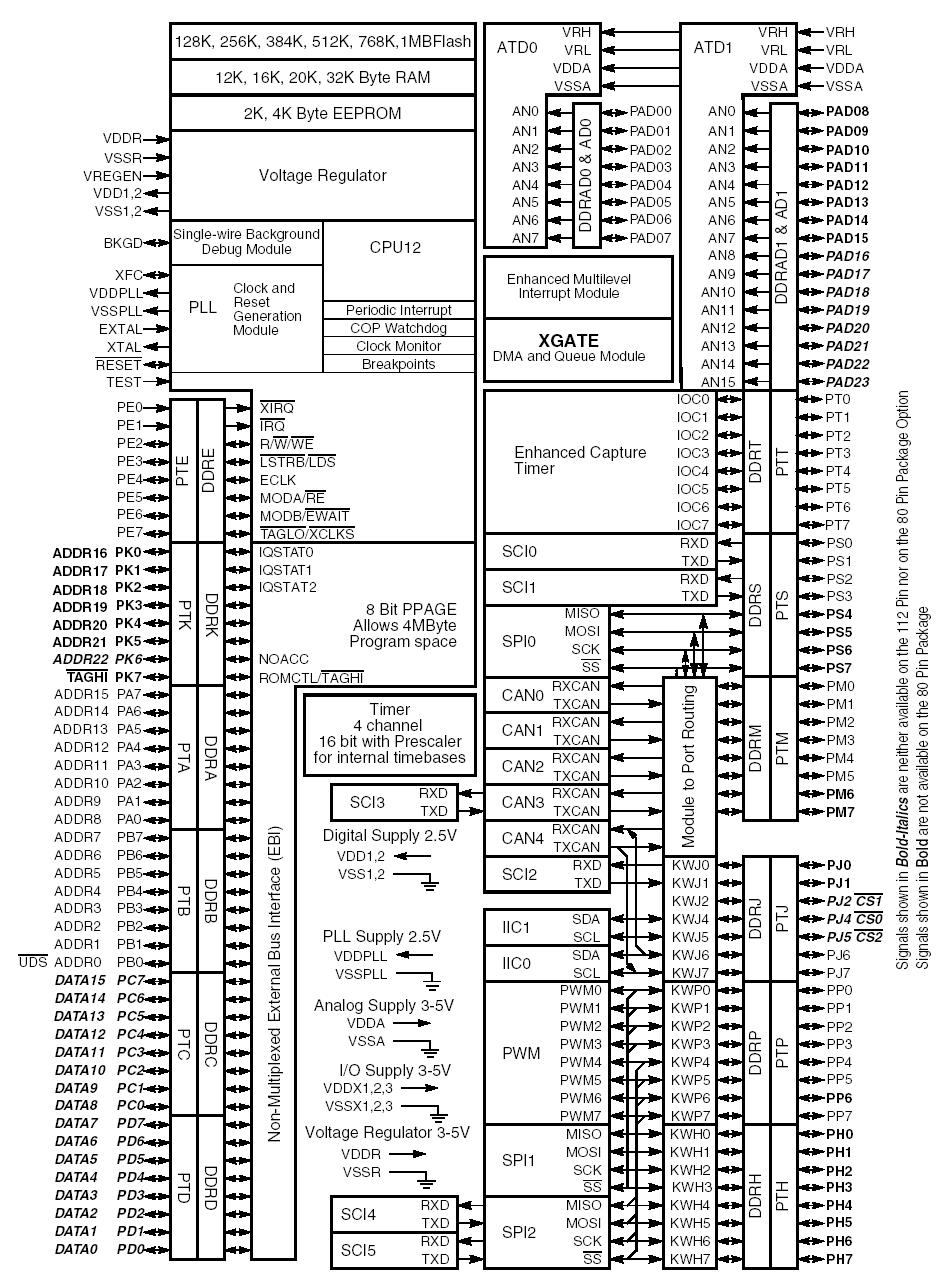
MCU Block Diagram
The following topics will be covered in detail in a future revision of this manual:
- some relevant Freescale docs & App Notes
- TA App Notes and Example code
Notes on Serial Monitor
The Adapt9S12XDP Microcontroller Module comes preprogrammed with a serial monitor in the topmost 2K of Flash memory. This monitor is an adaptation of the popular AN2548 monitor originally made for the HCS12 series. However it has been modified to work with the S12XDP CPU. It is designed to function using the SCI0 interface at 115200 baud, at 40 MHz. The current version, and the one recommended for use, is Version 2.3 or later. Earlier Adapt9S12XDP boards came with Version 2.2 or lower, which only operates at 24 Mhz. If your board has the older version, it is highly recommended that this be upgraded. Changing the serial monitor in Flash will require the use of a BDM pod, such as the Technological Arts USBDMLT. The serial monitor will also have to reinstalled if you need to use a different SCI port, different baud rate, or different CPU clock speed. You can download the serial monitor files, which include source and several S-record variants, from Technological Arts at:
http://support.technologicalarts.ca/docs/Adapt9S12X/S12XD/SerialMonitorXD/